(China (Mainland))

Product Summary
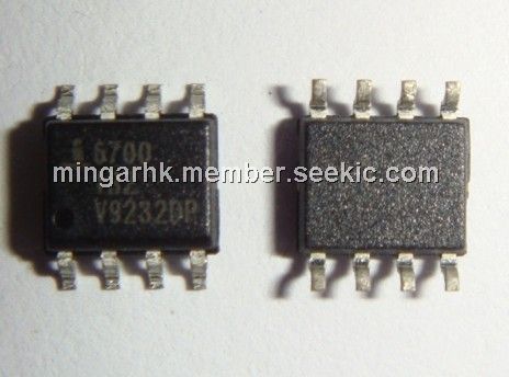
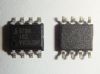
The ISL6700 is an 80V/1.25A peak, medium frequency, low cost, half-bridge driver IC available in 8-lead SOIC and 12-lead QFN plastic packages. The low-side and high-side gate drivers are independently controlled and matched to 25ns. This gives the user maximum flexibility in dead-time selection and driver protocol. Undervoltage protection on both the low-side and high-side supplies force the outputs low. Non-latching, level-shift translation is used to control the upper drive circuit. Unlike some competitors, the high-side output returns to its correct state after a momentary undervoltage of the high-side supply.
Parametrics
Absolute Maximum Ratings:
(1)Supply Voltage, VDD (Note 1):-0.3V to 16V;
(2)LI and HI Voltages (Note 1):-0.3V to VDD +0.3V;
(3)Voltage on HS (Note 1):0V to 80V;
(4)Voltage on HB (Note 1):VHS-0.3V to VHS+VDD;
(5)Voltage on LO (Note 1) :VSS-0.3 to VDD+0.3V;
(6)Voltage on HO (Note 1):VHS-0.3V to VHB+0.3V;
(7)Phase Slew Rate:20V/ns;
(8)Supply Voltage, VDD:9V to 15V;
(9)Voltage on HS :0V to 75V;
(10)Voltage on HS (Note 2):(Repetitive Transient) -1V to 80V;
(11)Voltage on HB:VHS+7.5V to VHS+VDD;
(12)Thermal Resistance (Typical):SOIC (Note 3):θJA=95 θJC (℃/W);
(13)Max Power Dissipation at 25℃ in Free Air (SOIC, Note 3).:1.316W;
(14)Max Power Dissipation at 25℃ in Free Air (QFN, Note 4):2.976W;
(15)Maximum Storage Temperature Range:-65℃ to +150°℃;
(16)Maximum Junction Temperature Range:-40℃ to +150℃;
(17)Maximum Lead Temperature (Soldering 10s):+300℃ (SOIC - Lead Tips Only)
NOTES:
1. All voltages referenced to VSS unless otherwise specified.
2. Based on VDD=15V. The magnitude of the allowable negative transient on the HS pin is a function of the VDD supply voltage.VHS<15.6VVDD+ VF, where VHS is the magnitude of the allowable negative transient and VF is the forward voltage drop of the bootstrap diode.
3. θJA is measured with the component mounted on a high effective thermal conductivity test board in free air. See Tech Brief TB379 for details.
4. θJA is measured in free air with the component mounted on a high effective thermal conductivity test board with “direct attach” features. θJC, the “case temp” is measured at the center of the exposed metal pad on the package underside. See Tech Brief TB379.
Features
(1)Drives 2 N-Channel MOSFETs in Half-Bridge Configuration;
(2)Space Saving SO8 and Low RC-S QFN Packages;
(3)Phase Supply Max Voltage to 80VDC;
(4)Bootstrap Supply Max Voltage to 96VDC;
(5)Drives 1000pF Load with Rise and Fall Times Typ. 15ns;
(6)TTL/CMOS Compatible Input Thresholds;
(7)Independent Inputs for Non-Half-Bridge Topologies;
(8)No Start-Up Problems;
(9)Low Power Consumption;
(10)Wide Supply Range;
(11)Supply Undervoltage Protection;
(12)QFN Package: Compliant to JEDEC PUB95 MO-220 QFN;Quad Flat No Leads - Package Outline;
(13)Pb-Free Available (RoHS Compliant)
Diagrams
<IMG border=0 src="http://www.seekic.com/uploadfile/ic-mfg/2012864632725.jpg">
| Image | Part No | Mfg | Description |  |
Pricing (USD) |
Quantity | ||||||||||||
|---|---|---|---|---|---|---|---|---|---|---|---|---|---|---|---|---|---|---|
 |
 ISL6700IBZ |
Intersil |
Power Driver ICs 75V/1 25A PEAK H-BRDG DRVR |
Data Sheet |
|
|
||||||||||||
 |
ISL6700IBZ-T |
Intersil |
Power Driver ICs 75V 1.25A PEAK HALF BRDG DRVR |
Data Sheet |
|
|
||||||||||||